Using the app, licences, FEA estimates and 3D export: choose a topic, then expand a question.
No results. Try a shorter or different search term.
Using ToolScan3D
I would like to rearrange the buttons on my screen.
Hold your finger on the screen for 5 seconds. A button grid appears, allowing you to drag the buttons to the positions you prefer. The centre of the screen is reserved for the default layout and the Done button, so you cannot place buttons there. When you have finished rearranging them, press Done in the centre.
How does a tool photograph become a 3D model?
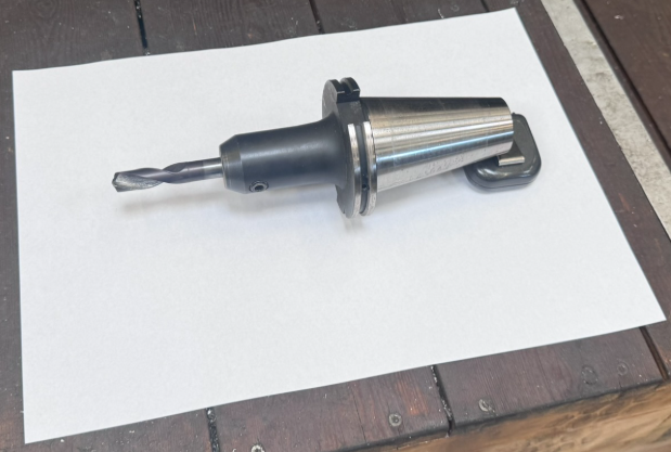
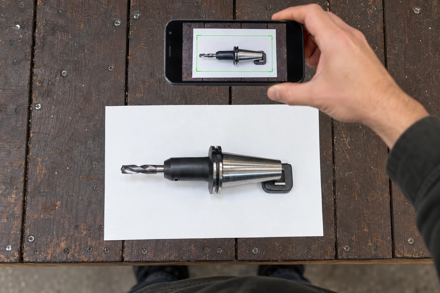
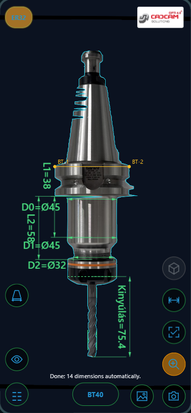
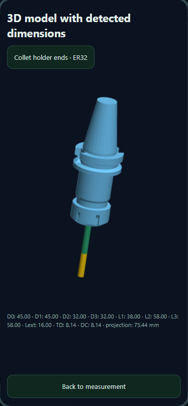
Prepare the reference sheet and tool, select the machine interface and take a photograph. Review the recognised type and estimated dimensions, correct them where necessary, then create the 3D toolholder–tool assembly.
What if recognition selects the wrong tool or holder?
Select the correct type manually and review its dimensions. The machine-side interface, such as BT40, and the tool-clamping system, such as ER32, are two different inputs.
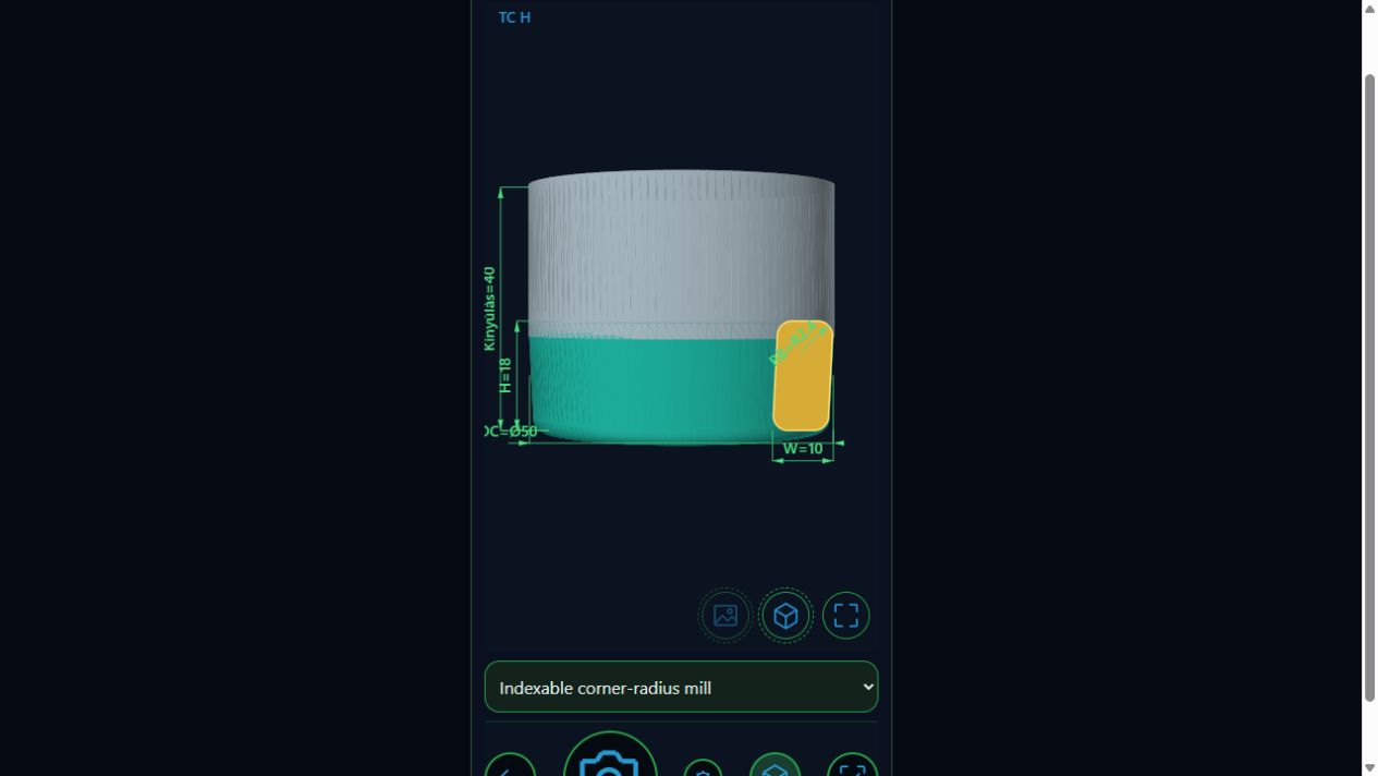
How can I edit dimensions in the 3D library?
Change an editable dimension in its input field. In the web preview, you can also click a dimension value to edit it: Enter applies the change and Esc cancels it. Not every dimension of a fixed manufacturer geometry can be changed.
Is the website demo the same as the full mobile app?
The website demo illustrates the workflow using sample images. A camera, AI or export button in the demo does not by itself mean that it starts a real service. Actual capabilities depend on the app release and your current access.
Where can I find the iOS and Android versions?
Check the downloads section for iOS and Android access. Use the verified release or store links published there. A development demonstration does not automatically mean that the app is publicly available in a store.
STL and STEP model generation are included in the base licence. Actual use also requires the permissions applicable to your account, app release and operating mode.
If the company buys licences, do colleagues need to buy them again?
The company administrator assigns available seats to colleagues. A colleague does not need to buy a permission already provided by the company. Base-licence and add-on assignments must be checked separately.
We bought a module, but a colleague cannot access it. What should we check?
Check that the colleague signed in with the correct Control account and that the company administrator assigned the required seat and module. Purchasing and assigning a colleague's permissions can be separate steps.
What is AI credit used for?
AI credit relates to paid image-analysis and identification usage. Buying an export module does not provide unlimited AI use. Check the current usage and top-up terms in your account and purchase summary.
How can I check what my trial or subscription allows?
Check the licence status, assigned modules and remaining allowances shown in your account. A feature list in a demonstration does not activate permissions. Ask your company administrator or support if the displayed access differs from what you expect.
Does Shopfloor include every CAM and CNC module?
No. Shopfloor and the individual CAM/CNC modules are separate permissions. A Shopfloor-dependent CAM/CNC workflow requires both Shopfloor and the selected connector module; always check the current product prerequisites.
Using FEA and FEA Pro
What can FEA and FEA Pro be used for?
FEA illustrates the physics behind cutting through estimates of forces, stresses, deformation and vibration. It can help compare settings and understand relationships, but its results are not measurements or safety certificates.
Actual cutting depends on material condition, tool and coating properties, cutting-edge geometry and wear, clamping and machining conditions. The calculation represents these effects only within the documented scope of its model.
What should I check before an FEA calculation?
Review the tool and holder geometry, overhang, material data, selected tool and coating data, cutting inputs and their units. Missing or uncertain inputs also limit the reliability of the result.
Is Pro always more accurate than the Basic calculation?
That is not guaranteed. Basic and Pro both produce estimates; neither method can be expected to agree better under every material and machining condition. Interpret each result together with the model assumptions and its inputs.
Is the deformation shown on the model displayed at its true scale?
The illustration may exaggerate deformation. Evaluate the numerical value, unit and scale indication rather than judging the result solely by the visible displacement in the drawing.
Where can I find published measurements and references?
Expand the relevant material-group comparison in the FEA estimation section. Published measurements and calculated estimates are shown separately, with links to the original publications. An experimental comparison does not establish the general accuracy of the entire FEA.
Can I start machining directly from an FEA result?
An estimate alone is not sufficient to approve machining. Independently check the actual tool, clamping, machine, material and process against manufacturer requirements and local safety procedures.
Exporting a 3D model
Which export format should I choose?
Choose a format supported by the target system. STL transfers a triangle mesh and STEP transfers CAD geometry; GTC and CAM/CNC connectors serve different data-transfer needs. Check the formats and modules supported by the current release.
Does STEP export make photo-estimated dimensions more accurate?
No. Export transfers the geometry and parameters already present in the model. STEP does not automatically correct a wrong dimension or tool type. Check the inputs and assembly first.
What should I check when exporting a toolholder–tool assembly?
Check the holder and tool identities, dimensions, overhang, connection and reference position. Also review the imported model in the target system, especially its units, orientation and origin.
Why can I not see every CAM or CNC output?
Available outputs depend on supported systems, enabled modules, account permissions and the installed release. A familiar manufacturer name or a different purchased module does not automatically provide access to every machine profile.
Does exporting a 3D model create a ready-to-run CNC machining program?
An STL or STEP model by itself contains geometry. It does not replace CAM process planning, the correct postprocessor, machine-specific settings or machining verification.
Inserts and the 3D library
What does the ISO checkbox do in the insert settings?
ISO mode ties the dimensions to the standard geometry of the selected insert shape. Insert height is then calculated and cannot be edited directly. The size field requests the parameter appropriate to that shape in millimetres, not its ISO size code.
Yes. In custom dimensioning, the permitted fields can be edited manually. The resulting geometry angles are shown in parentheses alongside the shape's nominal ISO angles, making any difference visible.
Why does the name show 80°/100° while the installation rotation is 65°?
80°/100° denotes the insert's nominal internal angles. Installation rotation controls its position in the assembly. Internal angles, installation rotation and cutting-edge clearance are different geometric properties.
Is the entered size the inscribed-circle diameter for every insert?
No. Many insert shapes use an inscribed-circle diameter, while others use a different standard parameter. Follow the field label and the selected shape's description; do not automatically treat an ISO size code as millimetres.
What if one size is not enough to define the ISO shape?
The editor must unlock custom dimensioning so that you can provide the missing dimensions. Without a catalogue template, an assumed aspect ratio must not be used to produce definitive ISO geometry; check the manufacturer's data separately.
Estimation and calibration
Is a dimension obtained from a photograph a measured result?
ToolScan3D produces preliminary geometric estimates from photographs. These are not certified dimensional measurements or guaranteed accuracy. Verify important dimensions using suitable physical instruments and original manufacturer data.
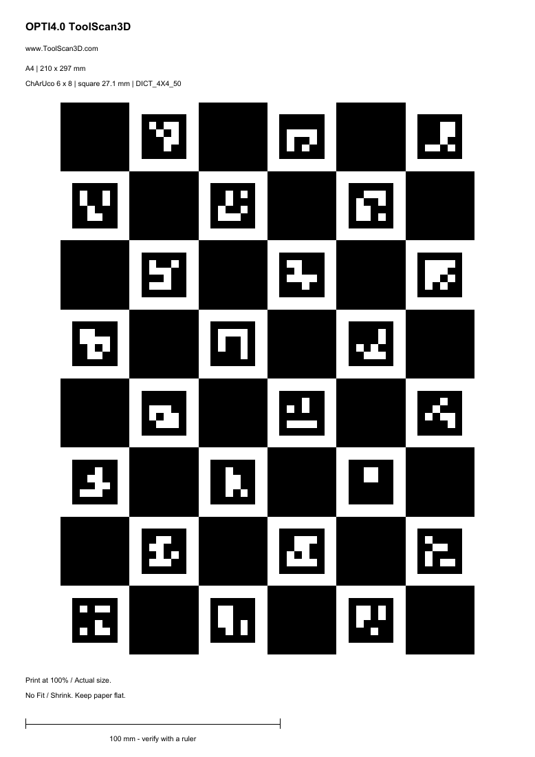
Why do the reference sheet and print scale matter?
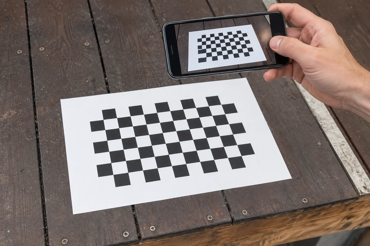
The estimate relies on the actual dimensions of the specified reference. Use a flat, clean sheet and check its size and print scale. An incorrectly sized or uneven sheet can distort the estimate.
No. Correct calibration can improve estimates but does not remove every source of error. Perspective, lens distortion, lighting, shadows and reference placement still affect the result.
Place the reference sheet on a flat surface and keep the tool axis parallel to it where possible. Position the camera above the tool and use a sharp image with even lighting. Avoid digital zoom and follow the app's capture instructions.
What should I check before using the model in the workshop?
Verify actual dimensions, tool and holder types, the assembly, reference position and exported data. Photo estimates and FEA estimates, even together, do not replace independent verification of the actual assembly and process.
FROM YOUR WORKSHOP TO A DIGITAL TOOL
Your tool. Digitised.
A photo from your phone. Dimensions, recognition and a 3D tool model in one workflow.
Meet OPTI4.0 ToolScan3D. Digitise tools and holders on iOS and Android.
ToolScan3D produces preliminary estimates from photographs, not exact measurement results or guaranteed accuracy.Estimation and calibration
Fmax, Ap/Ae and vibration optimisation; fracture-limit estimates
−
✓
Printing, company records and version history
−
✓
Windows / CAM FEA
−
✓
Custom workpiece materials, tool materials and coatings
−
✓
Cross-hole drilling analysis
−
In development
Estimates for supported tools and models. Thread forming is excluded. Company editing requires permission. Availability depends on the release.
OPTI4.0 TOOLSCAN3D · FEA
FEA · tools and capabilities
Calculation capabilities for 19 tool types. Checkmarks identify capabilities implemented and tested in source; check the released application version separately.
Development status · 19 November 2026. ✓ does not mean production or TestFlight availability and does not grant a licence.
Scroll horizontally to see the full table.
Capabilities by tool type
Legend and detailed conditions
Legend and detailed conditions
Platforms and release status
Platforms and release status
Calculation limits
Calculation limits
01Photo-based digitisation
02AI-assisted identification
033D and CAD/CAM export
04Shared company access
WHO IT HELPS
Real tools. Shared digital data.
From CAM programming to tool preparation: use the checked geometry of the assembly that is actually on your machine.
FEA Pro
Deformation shown at an exaggerated scale
For manufacturing engineers
Find better cutting conditions
Compare how cutting parameters affect the tool, holder and workpiece. FEA Pro visualizes estimated stresses, deformation and vibration to support your process choices.
See the trade-offs. Make better-informed process decisions.
For CAM programmers
Bring your workshop tools into CAM
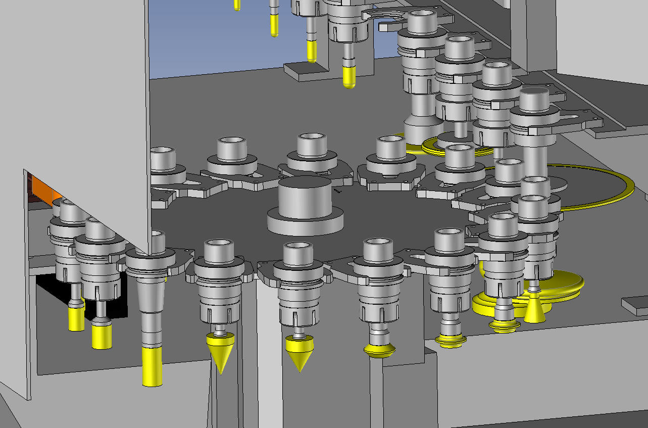
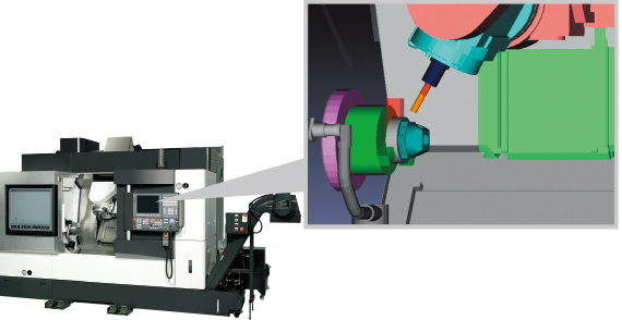
Program with greater confidence using realistic 3D models of the tool and tool holder. CAM simulation with the actual assembly helps identify and avoid collisions, supporting the creation of collision-free toolpaths.
Less manual modelling. A better prepared simulation.
Prepare tool geometry for supported controllers with the appropriate CNC module. Compatibility depends on the controller, its collision-checking options and the enabled export adapter.
Use checked assembly data in the machine’s own verification workflow.
For tool preparation and workshop teams
Clear assembly drawings at the machine
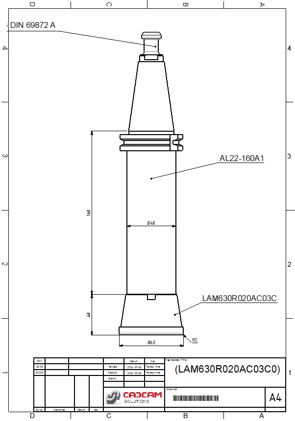
Create a dimensioned drawing of the tool and holder. Clearly recorded diameters, overhang and component choices help with tool preparation, handover and repeat setups.
One shared reference from preparation to the next shift.
Check dimensions, reference positions and exported geometry in the target system before collision checking. Photo-based models are preliminary estimates. ToolScan3D supplies geometry; collision checking is performed by your CAM or CNC system.
Print at 100% actual size without fit-to-page scaling. Check the printed reference dimensions and place the sheets flat.
02
Capture the calibration pattern
Following the app instructions, photograph the calibration sheets across the image area. Keep the camera, lens and zoom unchanged and use even lighting.
03
Apply the matching profile
Use the calibration profile matching the device, camera, lens, image resolution and zoom. Verify the result against independent measurements.
Calibration can improve estimates, but does not guarantee accuracy or replace a calibrated measuring instrument.
 FEA Pro